Radii, angles and distances
Evaluate geometric elements from a measured 2D profile, including radii, angles and linear distances. Stylus geometry and contact access determine the profile that can be acquired.
 K K Geo System | 3D Scanning & Metrology Solutions India
Measuring Systems · MarSurf
Evaluate profile geometry and choose the right measurement approach for your component. Compare contour-focused systems and combined contour-and-roughness systems together.
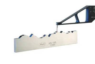
Evaluate geometric elements from a measured 2D profile, including radii, angles and linear distances. Stylus geometry and contact access determine the profile that can be acquired.
Compare a measured contour with a nominal profile or fitted geometric elements using suitable evaluation software. Define alignment, reference geometry and the required deviation output.
On suitable configurations, evaluate contour geometry and surface roughness using the appropriate probes and measurement settings for each task.
| Family | Starting requirement | Published options | Selection focus |
|---|---|---|---|
| MarSurf CD 140 / CD 280 | Contour-focused inspection | 140 / 280 mm measuring path | Assess profile access, probe selection and positioning. |
| MarSurf CD 140 AG / AF | Manual or flexible-stand configurations | Variants with / without PC; roughness options listed | Specify the stand, PC and measurement functions together. |
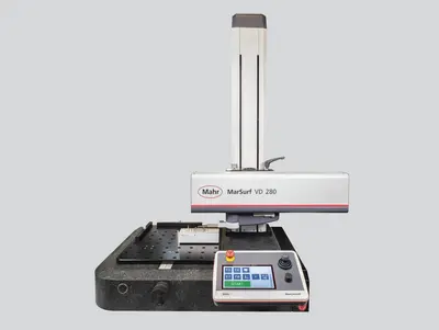
| MarSurf VD 140 / VD 280 | Contour and roughness on one platform | 140 / 280 mm measuring path | Compare the required probe systems and changeover workflow. |
| MarSurf LD 140 / LD 280 | Simultaneous contour and roughness | 140 / 280 mm tracing length | Evaluate combined measurement against the surface and tolerance requirements. |
Measuring path is not the complete workpiece envelope. Confirm part size, weight, clamping, vertical access, stylus geometry and evaluation software for the proposed configuration.
Supply the drawing, nominal geometry, tolerance and required report. Mark which features require contour evaluation and which require roughness.
Review the stylus path, slopes, recesses and fixture clearance. Confirm that the proposed probe can reach the required profile.
Describe batch size, changeovers and operator involvement. Agree workholding, positioning and measurement sequences.
Specify software, evaluation methods, reporting, reference artefacts and documentation as part of the proposed system.
Compare CD for contour-focused inspection, VD when contour and roughness are needed on one platform, and LD for simultaneous contour and roughness measurement. The final choice depends on the drawing features, tolerances, stylus access and inspection cycle.
Use the length of the profile to be traced, including the positioning needed for the measurement. Also check part height, weight, fixture space and probe access. A longer measuring path does not by itself confirm that the component fits.
Send the component drawing, overall size and weight, required radii or angles, tolerances and daily inspection quantity. If roughness is also required, include its parameters and measurement conditions.
Send a drawing, part dimensions and weight, required profile features, tolerances and inspection volume.
Model availability, accessories and lead time are confirmed with the quotation.
Family information: Tactile contour category, MarSurf CD 140, MarSurf VD 140, MarSurf LD 140. These are manufacturer-listed options; India supply and configuration require confirmation.
Product photographs: Mahr. Images illustrate product families; supplied equipment and accessories depend on the selected configuration.