Height, step and depth
Measure vertical dimensions relative to a surface-plate datum. Select a probe or insert that can contact the required faces and reach the feature.
 K K Geo System | 3D Scanning & Metrology Solutions India
TESA · Vertical dimensional measurement
Compare TESA manual 1D height gauges, manual and motorised instruments with 2D functions, and compact measuring stations. Choose around the dimension, tolerance and inspection workflow.
Measure vertical dimensions relative to a surface-plate datum. Select a probe or insert that can contact the required faces and reach the feature.
Determine accessible internal or external diameters and centre heights using opposing contacts and the appropriate probing function.
On suitable models, evaluate feature relationships using the instrument’s 2D measurement workflow. Establish the references and workpiece orientation required by that method.
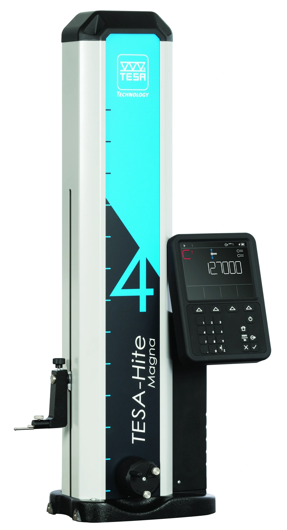
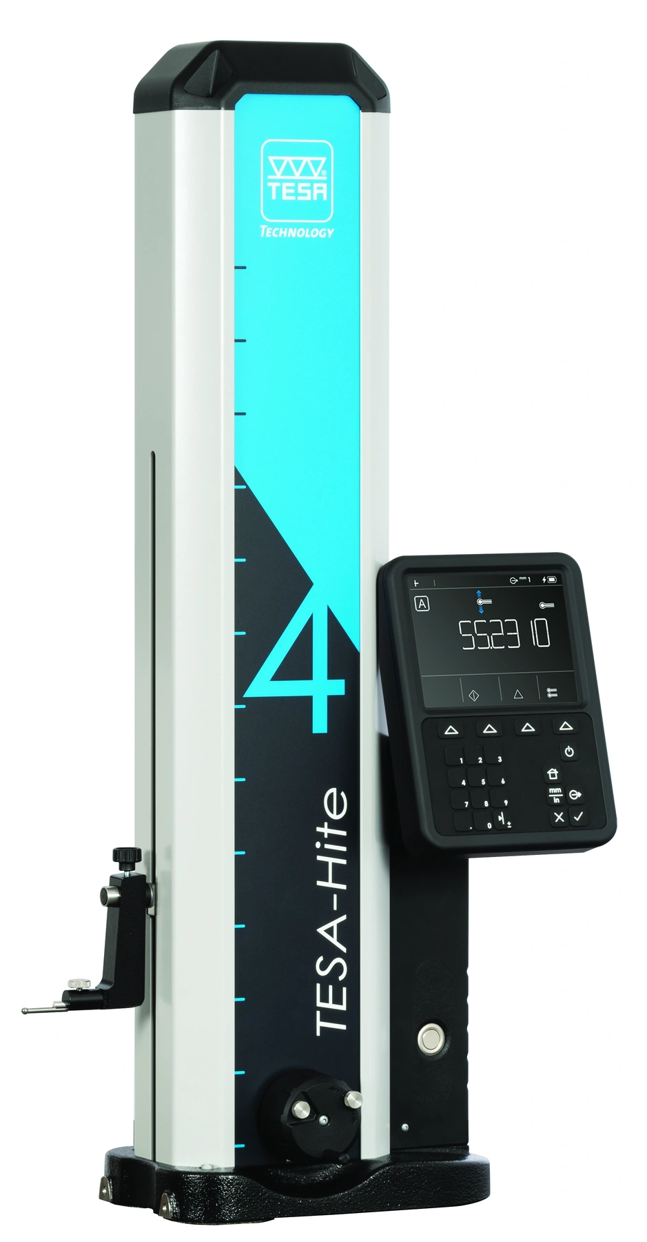 TESA-HITE / TESA-HITE MAGNA
Compare these families for vertical dimensional checks and the demands of the workshop environment.
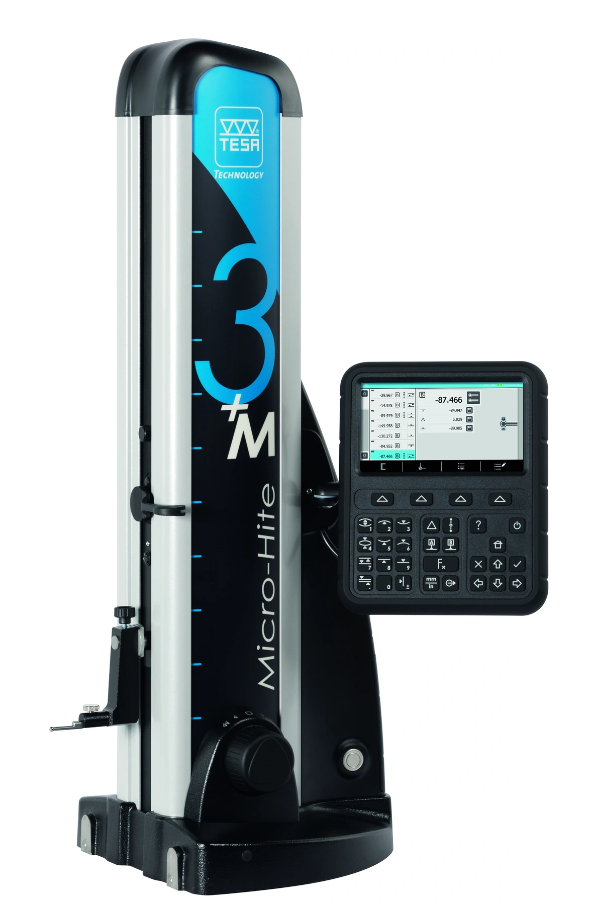
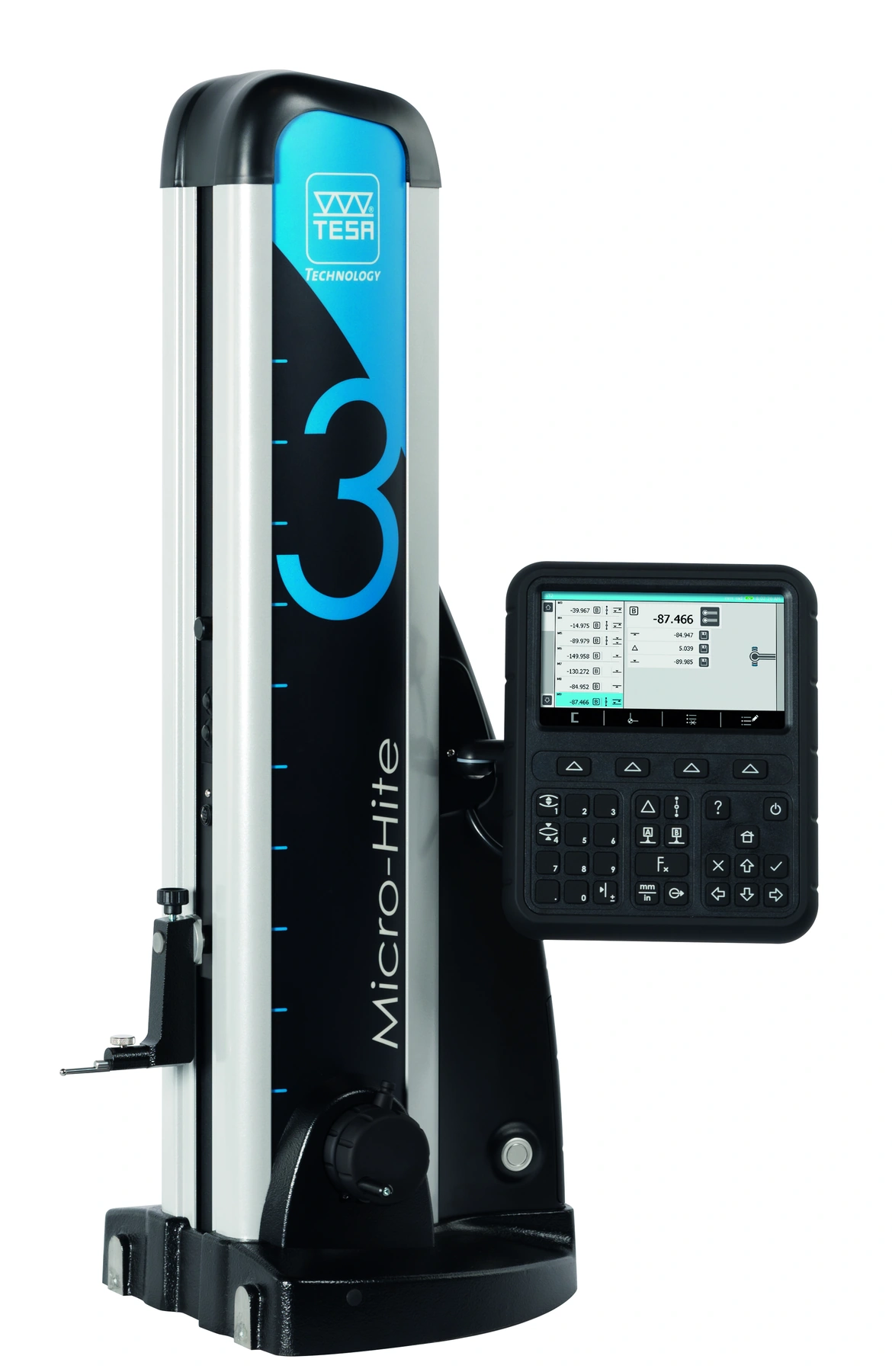 MICRO-HITE / MICRO-HITE+M
Compare manual and motorised probe movement alongside the required feature evaluation.
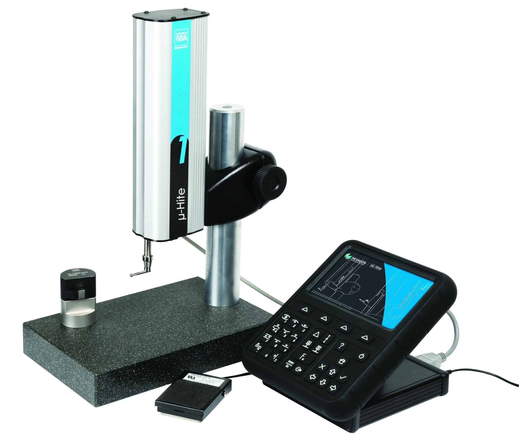 TESA µ-HITE
Consider a compact station for small parts and a defined measuring-head arrangement.
5 families
| Product family | Measuring approach | Model size / measuring range | Selection focus |
|---|---|---|---|
|
TESA-HITE |
Manual · 1D | 400 / 700Measuring range: 415 / 715 mm | Routine vertical dimensional inspection with manual probe movement. |
 TESA-HITE MAGNA |
Manual · 1D | 400 / 700Measuring range: 415 / 715 mm | Workshop inspection with the magnetic Magna-µ measuring system. |
|
MICRO-HITE |
Manual · 2D functions | 350 / 600 / 900Measuring range: 365 / 615 / 920 mm | Manual positioning with 2D evaluation; review fine-adjustment variants. |
|
MICRO-HITE+M |
Motorised · 2D functions | 350 / 600 / 900Measuring range: 365 / 615 / 920 mm | Motorised probe movement for workshop or inspection-room measurement. |
|
TESA µ-HITE |
Compact motorised station | µ-HITE stationMeasuring range: 100 mm | Small-part measurement; evaluate the measuring-head and complete-setup requirements separately. |
Ranges are for the catalogue variants shown, in the same order as the model sizes. Model size, usable contact access and measuring range are distinct selection details. Confirm the exact part number, permissible error and supplied configuration. Display resolution alone does not state measurement accuracy.
Provide the maximum height, bore sizes and contact locations. Check the usable measuring envelope with the selected probe, holder and workpiece position.
Review permissible error, repeatability and the complete measurement setup against the tolerance. Consider temperature, cleanliness and the condition of the surface plate.
Choose manual or motorised movement, then identify any 2D functions needed. Motorised movement does not by itself define automatic workpiece handling.
Specify the surface plate, reference artefacts, probe inserts and required documentation. Identify the receiving software and data interface if results must be transferred.
A suitable surface plate establishes the datum plane. Select the reference gauge and verification routine for the measuring method.
Match the measuring contact to bores, grooves or flat faces. Check holder interfaces, insert diameter and reach before specifying an accessory set.
Confirm the required TLC or USB connection on the selected model. Where wireless transfer is needed, include the compatible transmitter, receiver and receiving software.
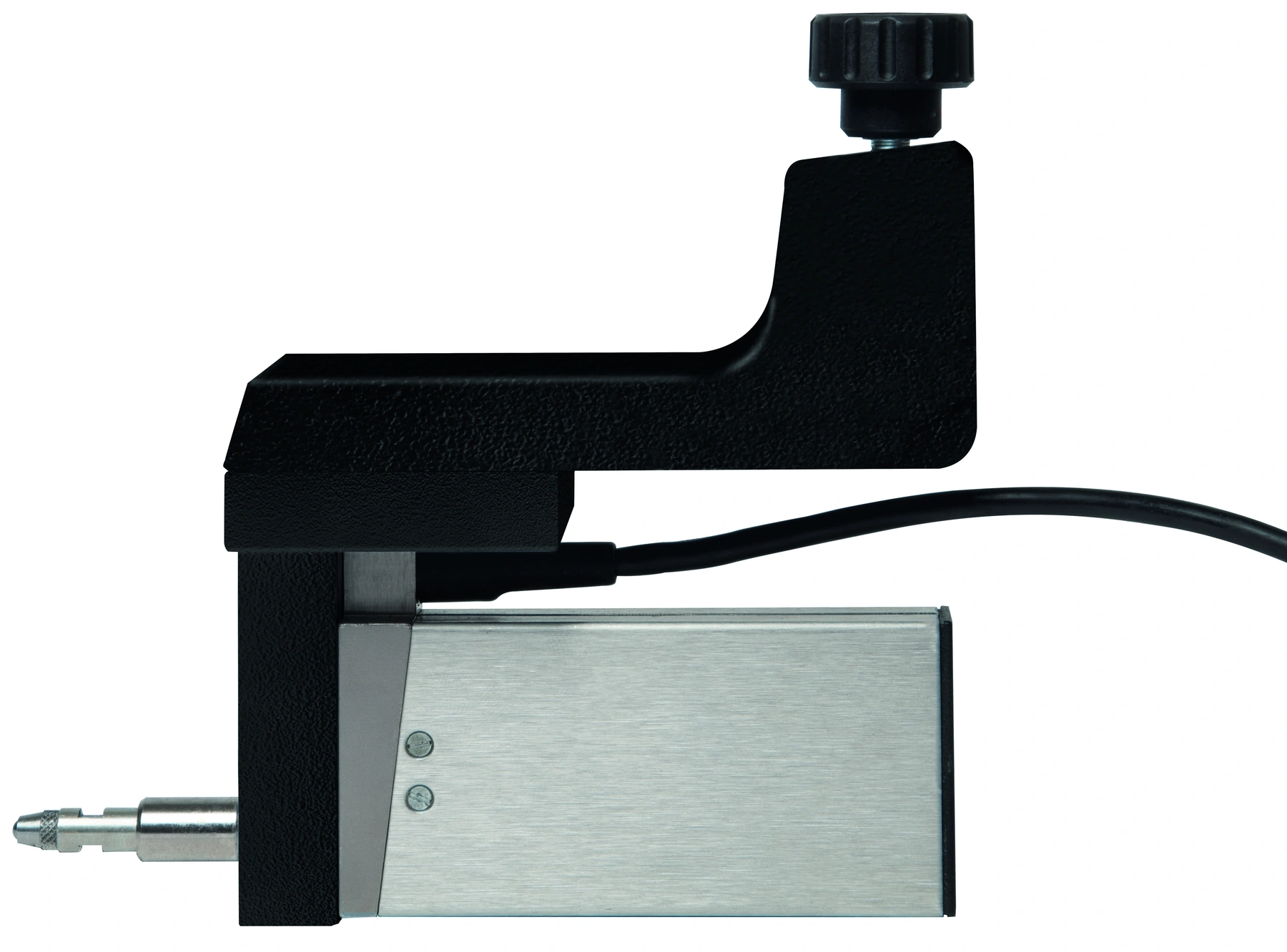
For component perpendicularity checks, review the compatible IG13 probe, holder, reference and evaluation method with the selected instrument. The instrument’s specified perpendicularity error is a separate specification.
For heights, steps and diameters from a reference plane, start with the required 1D functions. If the drawing calls for feature relationships such as centre distances or angles in a plane, review the 2D workflow available on MICRO-HITE, MICRO-HITE+M or the appropriate station configuration.
Model designations and stated measuring ranges can differ. The catalogue lists 415 mm for the TESA-HITE 400 and TESA-HITE MAGNA 400 variants. Confirm the exact measuring range and contact reach for your part.
Protection ratings apply to the specified part of the instrument. For example, the TESA-HITE MAGNA catalogue distinguishes IP65 for the panel from IP55 for the measuring system. Check the exact model specification for the proposed environment.
Specify the characteristic, tolerance and reference surface. Confirm the compatible probe, holder and measurement procedure with the instrument; the catalogue lists the IG13 probe and holder as accessories for the MICRO-HITE families.
Select the connection supported by the exact model and the receiving software. TLC-BLE transmitters, receivers and acquisition software are listed as accessories; confirm which items are included in the quotation.
Provide the drawing or feature list, maximum measuring height, bore diameters, tolerances, part size and inspection quantity. Include the surface-plate arrangement, manual or motorised preference, data needs and required calibration documentation.
Send the part drawing, measuring heights, diameters and tolerances, inspection quantity and any data-transfer requirement.
India availability, supplied accessories and lead time are confirmed with the quotation.
Product information and photographs: TESA height-gauge range and its technical catalogue. Photos are representative configurations. .