Lengths, widths and centre distances
Measure dimensions between visible edges or features using a measuring microscope or suitable optical system. Define the measurement plane and component alignment.
 K K Geo System | 3D Scanning & Metrology Solutions India
Measuring Systems · Mahr
Compare Mahr optical dimensional-measurement instruments for visible edges and geometric features. Evaluate measuring microscopes and automated variants around the part, illumination and inspection sequence.
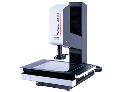
Measure dimensions between visible edges or features using a measuring microscope or suitable optical system. Define the measurement plane and component alignment.
Evaluate geometric elements from optically detected edges. Select illumination and magnification that provide reliable edge contrast on the actual component.
Inspect accessible geometry where contact probing could deform or obstruct the feature. Suitability depends on optical access, surface response and the required dimensional tolerance.
| Model / option | Range or configuration | Selection notes |
|---|---|---|
| MarVision MM 500 | Measuring microscope | M / L / XL variants: 200 × 100 / 300 × 200 / 400 × 250 mm X/Y ranges. |
| MarVision MM 500 CNC | CNC measuring microscope | The listed M / L / XL X/Y ranges are 200 × 100 / 300 × 200 / 400 × 250 mm. |
| Other 2D / 3D optical configurations | Application-based selection | Confirm the sensing method and available configuration for the required dimensions. |
Ranges refer to specific variants or sets. Confirm the exact model, configuration and accessories with your quotation.
Provide the material, finish and features to be detected. Evaluate illumination on the real component.
Compare the part envelope, fixture space and measuring range; nominal travel alone is not the usable inspection envelope.
Describe batch size, operator workflow, program reuse and reporting requirements.
A manual workflow may suit varied, lower-volume checks; CNC should be evaluated when repeated inspection sequences and program reuse are important. Compare both against the number of features, part mix and required throughput.
The listed M, L and XL variants provide 200 × 100, 300 × 200 and 400 × 250 mm X/Y ranges. Allow for the fixture and the travel needed to reach every feature, not just the component’s overall size.
Edge detection depends on material, surface finish, lighting and geometry. Provide a sample or clear images identifying the features, especially for reflective parts or poorly defined edges, so the illumination and measurement method can be assessed.
Part drawing, dimensions, material, visible features, tolerance, batch size and report format.
Model availability, accessories and lead time are confirmed with the quotation.
Range references: Mahr microscope product listing. Manufacturer-listed systems and options are subject to India availability and configuration confirmation.
Product photographs: Mahr. Images illustrate product families; supplied equipment and accessories depend on the selected configuration.