 K K Geo System | 3D Scanning & Metrology Solutions India
Precision 3D Laser Scanning & Dimensional Metrology Solutions
K K Geo System | 3D Scanning & Metrology Solutions India


Mechanical quality inspection · Scan-to-reference comparison
K K Geosystem offers mechanical-component inspection using 3D scan data compared with an agreed CAD model or drawing reference. The scope can include surface-deviation views, selected sections and feature checks, with reporting defined around your inspection requirements and tolerances.
Offices in Ahmedabad and Jamshedpur support on-site assignments across India. Measurement suitability is reviewed before accepting the inspection scope.
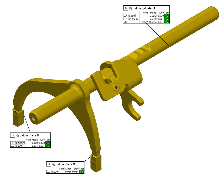
Consider this service when you need to compare accessible component surfaces with reference geometry and understand where deviations occur. Share the intended decision, such as pre-dispatch assessment or dimensional review, so the required checks can be defined.
| Customer inputs | Agreed evaluation | Report content |
|---|---|---|
| Reference CAD revision or dimensioned drawing | Compare the specified geometry | Identified reference and inspected areas |
| Datums or alignment requirements | Apply and document the agreed alignment | Alignment basis and comparison views |
| Features, tolerances and reporting requirements | Evaluate suitable agreed characteristics | Results, units and acceptance status where justified |
A report should identify the reference, alignment, units and colour scale. Acceptance depends on the specified tolerances and agreed evaluation rules. A colour plot should be read alongside those details rather than treated as a pass or fail image on its own.
Alignment choices affect comparisons. Datum-based or other specified alignment must be agreed for the purpose; a best-fit comparison should not silently replace a drawing’s datum requirements.
This page covers inspection built around scanned surface data. Portable CMM Inspection covers the separately scoped measurement of selected dimensions and features. The suitable method depends on the geometry, accessibility, tolerance and required evidence; a combined approach can be discussed when needed.
Scanning detail or point density is not, by itself, proof that a tolerance can be verified. No universal accuracy or acceptance claim is made for every component.
A dimensioned drawing may support selected checks. Full surface comparison requires suitable reference geometry. Send available references so the feasible evaluation can be defined.
Supply the required characteristics, datum system and applicable drawing requirements. Only evaluations supported by the agreed measurement method and data are included.
Send a sample and details of acquisition, units, references and required tolerances for review. Inspection suitability must be assessed before agreeing a reporting scope.
Provide component photographs and dimensions, quantity, location, CAD or drawing revision, features and tolerances, alignment requirements, desired report and deadline. Confidential transfer arrangements can be agreed first.
Mechanical Component 3D Scanning · Reverse Engineering & Scan-to-CAD · Jig & Fixture Verification
Offices in Ahmedabad and Jamshedpur. On-site services across India. Remote modelling and drawing services for overseas customers using customer-supplied data.
Email inquiry@kkgeosystem.com or call +91 98244 40077.
Please include the service required, location, approximate size or data extent, required outputs and target date. For confidential or large files, contact us to agree the transfer method.